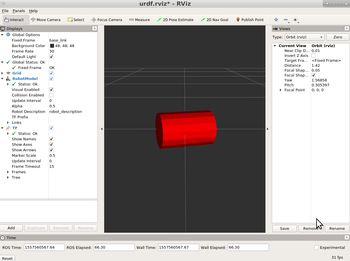
ROS course 014: URDF Part 2
1. Environment
This post is tested under the following Environment:
| Item | Value |
|---|---|
| CPU | AMD Ryzen 5 2600 |
| Ubuntu | 18.04 |
| ROS | Melodic |
For installation, see 02 Install. The source code of all parts is upload of github, see 11 git for more detail.
2. Summary
In this post, i’ll talk about:
- change visual feature of link
- change joint type into movable type
3. Change visual feature of link
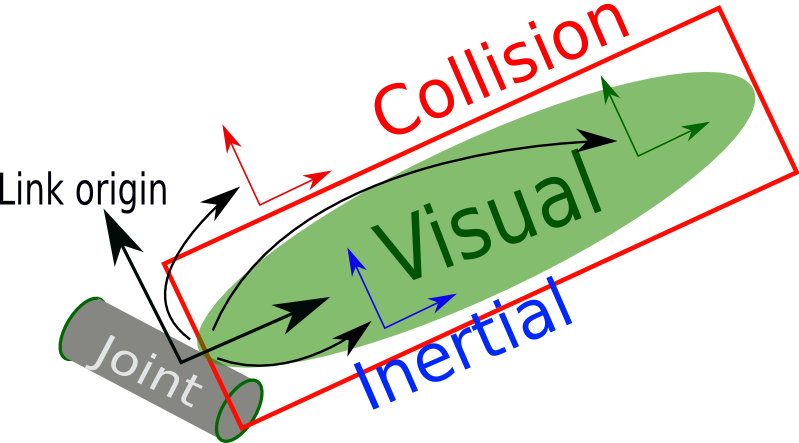
In the 13 urdf part 1, we created a 1 link model which is displayed as a simple red box. A link have inertial, visual, collision features . Let’s try edit some visual feature and see how these variable work. Reference of urdf can be found at urdf/XML/link, there’re several tags we can use to

3.1. Shape, color of object
urdf file is places at the following location
src/vis_lecture/
├── CMakeLists.txt
├── launch
├── package.xml
├── rviz
├── src
├── stl
├── urdf
│   ├── simple_body2.urdf     <- this file
└── xacro
simple_body2.urdf contain is as follow
<?xml version="1.0"?>
<robot name="test_robot">
  <link name="base_link"/>

  <joint name="body1_joint" type="fixed">
    <parent link="base_link"/>
    <child  link="body1_link"/>
  </joint>
  <link name="body1_link">
    <visual>
      <geometry>
        <box size="0.3 0.3 0.2"/>
      </geometry>
      <origin xyz="0 0 0" rpy="0 0 0"/>
      <material name="red">
        <color rgba="1.0 0.0 0.0 2.0"/>
      </material>
    </visual>
  </link>

  <joint name="body2_joint" type="fixed">
    <parent link="base_link"/>
    <child  link="body2_link"/>
    <origin xyz="0.5 0 0" rpy="0 0 0"/>
  </joint>
  <link name="body2_link">
    <visual>
      <geometry>
        <sphere radius="0.2"/>
      </geometry>
      <origin xyz="0 0 0" rpy="0 0 0"/>
      <material name="green">
        <color rgba="0.0 1.0 0.0 2.0"/>
      </material>
    </visual>
  </link>

  <joint name="body3_joint" type="fixed">
    <parent link="base_link"/>
    <child  link="body3_link"/>
    <origin xyz="-0.5 0 0" rpy="0 0 0"/>
  </joint>
  <link name="body3_link">
    <visual>
      <geometry>
        <cylinder length="0.3" radius="0.1"/>
      </geometry>
      <origin xyz="0 0 0" rpy="0 0 0"/>
      <material name="blue">
        <color rgba="0.0 0.0 1.0 2.0"/>
      </material>
    </visual>
  </link>
</robot>
Display on rviz
roscd vis_lecture/urdf/
roslaunch urdf_tutorial display.launch model:=simple_body2.urdf
The output on rviz is as follow

The code detail for each object is as follow
- Left green sphere
<link name="body2_link"> <visual> <geometry> <sphere radius="0.2"/> </geometry> <origin xyz="0 0 0" rpy="0 0 0"/> <material name="green"> <color rgba="0.0 1.0 0.0 2.0"/> </material> </visual> </link> - Middle red box
<link name="body1_link"> <visual> <geometry> <box size="0.3 0.3 0.2"/> </geometry> <origin xyz="0 0 0" rpy="0 0 0"/> <material name="red"> <color rgba="1.0 0.0 0.0 2.0"/> </material> </visual> </link> - Right blue cylinder
<link name="body3_link">
  <visual>
    <geometry>
      <cylinder length="0.3" radius="0.1"/>
    </geometry>
    <origin xyz="0 0 0" rpy="0 0 0"/>
    <material name="blue">
      <color rgba="0.0 0.0 1.0 2.0"/>
    </material>
  </visual>
</link>
Please see urdf/XML/link and try to change shape of object and colors.
3.2. Coordination, fixed axis roll
Inside urdf/XML/link, we have the following tags used to set variable of initial coordinator and fixed axis roll of object.
<origin> (optional: defaults to identity if not specified)
  The reference frame of the visual element with respect to the reference frame of the link.
  xyz (optional: defaults to zero vector)
    Represents the $$x,y,z$$ offset.
  rpy (optional: defaults to identity if not specified)
    Represents the fixed axis roll, pitch and yaw angles in radians.
For a quick introduction about object coordinator and fixed axis roll please see img. In a short word : rpy is x, y, z axis clockwise rotation degree respectively.
Let’s try to edit xyz, and rpy to understand how object is put and rotated in the initial state. For example, with the urdf as follow
<robot name="test_robot">
  <link name="base_link"/>

  <joint name="body_joint" type="fixed">
    <parent link="base_link"/>
    <child  link="body_link"/>
  </joint>
  <link name="body_link">
    <visual>
      <geometry>
        <!-- <box size="0.3 0.3 0.2"/> -->
        <cylinder length="0.3" radius="0.1"/>
      </geometry>
      <origin xyz="0 0 0" rpy="30 30 30"/>
      <material name="red">
        <color rgba="1.0 0.0 0.0 2.0"/>
      </material>
    </visual>
  </link>
</robot>
we’ll have the following output :

4. change joint type into movable type
Up to now the joint between link is fixed and can not be moved. Let’s change type of joint into movable type :”revolute” and see how a robot joint should work. See joint for detail explaination
src/vis_lecture/
├── CMakeLists.txt
├── launch
├── package.xml
├── rviz
├── src
├── stl
├── urdf
│   ├── simple_body4.urdf     <- this file
└── xacro
The urdf is as follow
<robot name="test_robot">
  <material name="red">
    <color rgba="1.0 0.0 0.0 2.0"/>
  </material>

  <link name="base_link"/>

  <joint name="body1_joint" type="fixed">
    <parent link="base_link"/>
    <child  link="body1_link"/>
  </joint>
  <link name="body1_link">
    <visual>
      <geometry>
        <box size="0.1 0.1 0.5"/>
      </geometry>
      <origin xyz="0 0 0.25" rpy="0 0 0"/>
      <material name="red"/>
    </visual>
  </link>

  <joint name="body2_joint" type="revolute">
    <parent link="body1_link"/>
    <child  link="body2_link"/>
    <origin xyz="0.1 0 0.5" rpy="0 0 0"/>
    <limit lower="-1.5" upper="1.5" effort="0" velocity="0"/>
  </joint>
  <link name="body2_link">
    <visual>
      <geometry>
        <box size="0.1 0.1 0.4"/>
      </geometry>
      <origin xyz="0 0 0.2" rpy="0 0 0"/>
      <material name="red"/>
    </visual>
  </link>

  <joint name="body3_joint" type="revolute">
    <parent link="body2_link"/>
    <child  link="body3_link"/>
    <origin xyz="0.1 0 0.4" rpy="0 0 0"/>
    <limit lower="-1.5" upper="1.5" effort="0" velocity="0"/>
  </joint>
  <link name="body3_link">
    <visual>
      <geometry>
        <box size="0.1 0.1 0.4"/>
      </geometry>
      <origin xyz="0 0 0.2" rpy="0 0 0"/>
      <material name="red"/>
    </visual>
  </link>
</robot>
Run script
roscd vis_lecture/urdf/
roslaunch urdf_tutorial display.launch model:=simple_body4.urdf

Leave a comment