Polarization imaging
Summary
Challenges in inspection tasks
There’re challenge inspection tasks that a normal CMOS/CCD camera can not solve. Those challenge inspection tasks can be divided into 3 categories as below . Image source And Sony video
- Hidden stress in meterials
- Strong reflective surfaces
- Low contrast objects/surfaces
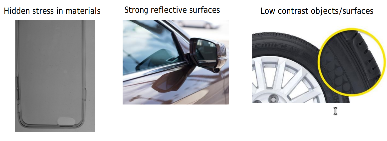
Why these inspection tasks are challenged ?
To answer this question, at first let’s take a look at how a digital camera capture image.
Inside every digital camera, there’s a electronic equipment that captures the incoming light rays and turns them into electrical signals. This light detector is one of two types, either a charge-coupled device (CCD) or a CMOS image sensor. The electrical signals are later convert into data and can be stream or stored as digital image.
So How can we capture image of inspected object ?. We point the camera into inspected object, then push the button. The camera will capture light ray came from inspected object. And, we’ll have a nice picture of inspected object. Such as the image below.

What could go wrong here?.
When light come to the surface of inspected object, it will be reflected/absorbed/refracted. If the light is reflected too much or absorbed/refracted too much, the surface detail of inspected object will be lost. Inspected object appeared on captured image will be flared or low in contrast. This will make image analysing become nearly impossible. You can see a list of image on link1 and link2 for a list of image.

How can we solve this problem?.
At this point, we can see that in those challenge inspectation task, surface detail of inspected object are flared or low in contrast. So we need to increase the surface detail of inspected object or reduce the light noise to capture better image.
There’re several approaches that could be used for this situation. Such as hyperspectral camera (increase information), 3d camera (increase information), polarization imaging (reduce nosie), etc. In the scope of this post, i will talk only about polarization imaging.
Polarization Imaging
Polarization imaging is a imaging technque that capture only certain part of input light ray. In the below image: the right images are captured by using polarization imaging. This cut of the flare inside image and capture a better and more vivid image. source
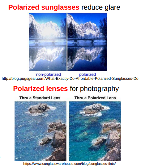
In photography, it’s very popular to use a polarizing filter to reduce flaring from sky/sea/water picture. source
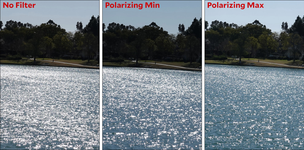
Polarization imaging usage
Polarization imaging can be used for belows tasks. Source: lucid vision lab
- Stress Inspection
- Reduce Reflection
- Improving Contrast
- Scratch inspection
- Object detection
Polarization theory
Light have Wave and Particle properties. Most sources of light are classified as incoherent and unpolarized (or only “partially polarized”) because they consist of a random mixture of waves having different spatial characteristics, frequencies (wavelengths), phases, and polarization states source .
Unpolarized light is un-consistent and noisy. So we need to convert it into polarized light to haverst consistent and stable light ray. The below figure simply illustrate the difference between unpolarized light and polarized light source: quora that illustrate the difference between unpolarized and polarized light.
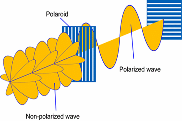
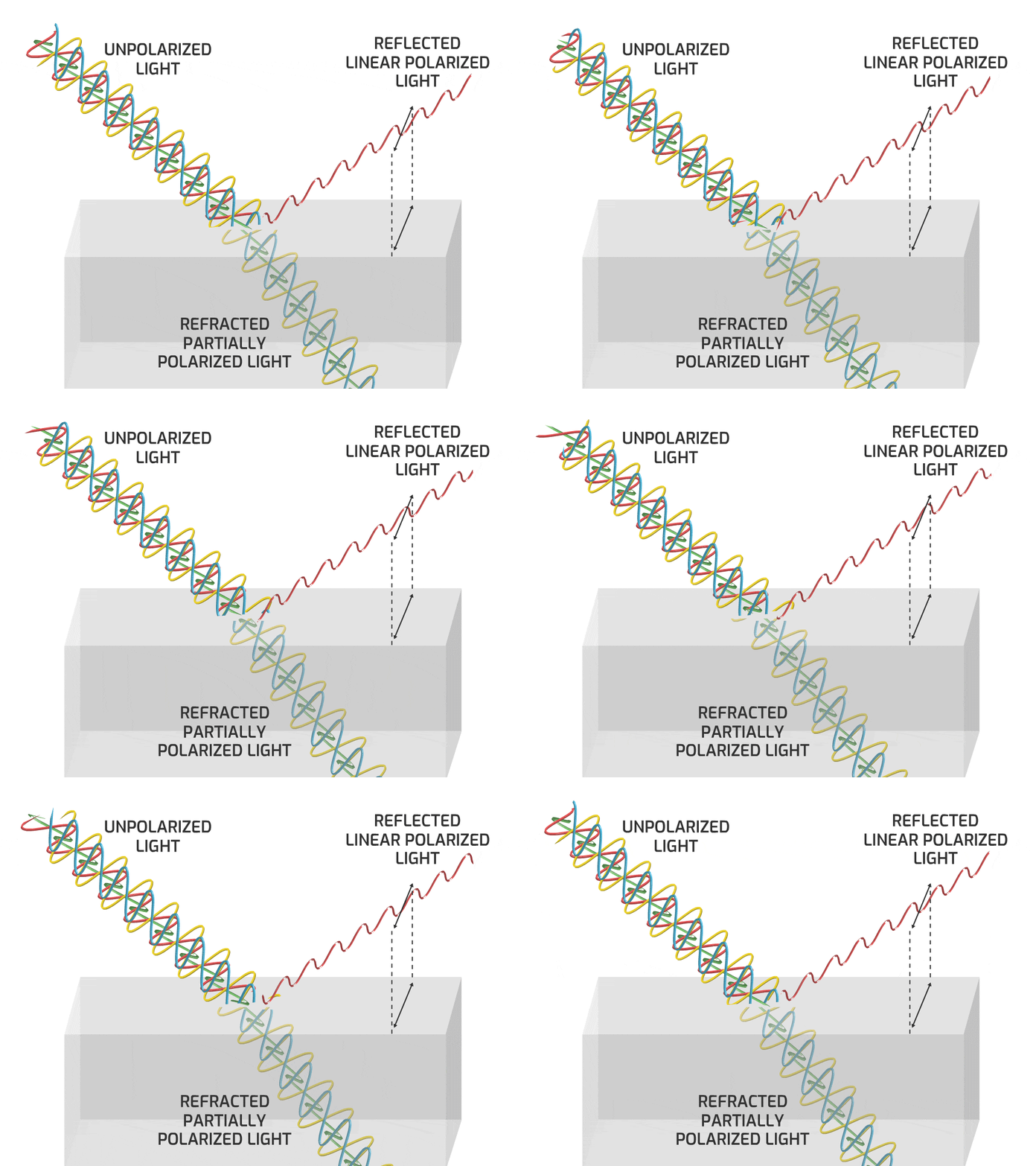
How to convert unpolarized light into polarized light ?. Unpolarized light can be converted into polarized light by using light reflection or refraction effect. For example, in the below image, the red part of light are extracted and become polarized light source: lucid vision labs .
How to apply polarization imaging?
There’re 2 approaches can be used to apply polarization imaging.
- polarizing lense
- polarization camera/sensor
Polarizing lense
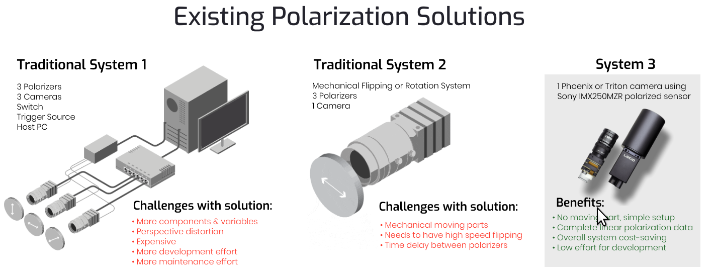
Tradition system use polarizing lense. The lenses are placed in front of camera so part of in-come light ray is filtered and result in more contrasted and clear image. This approach have 2 disadvantages as below.
- Expensive and hard to mainternance
- Can not completely reduce noise
Several lenses need to be integrated into vision system. This increase the total cost and number of equipments. Finally results is a vision system that’s expensive and hard to mainternance
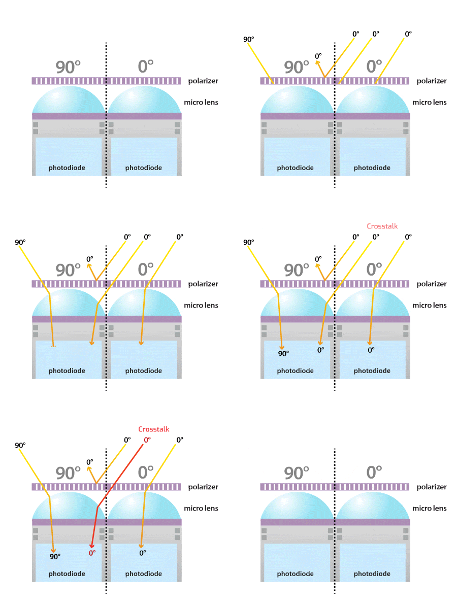
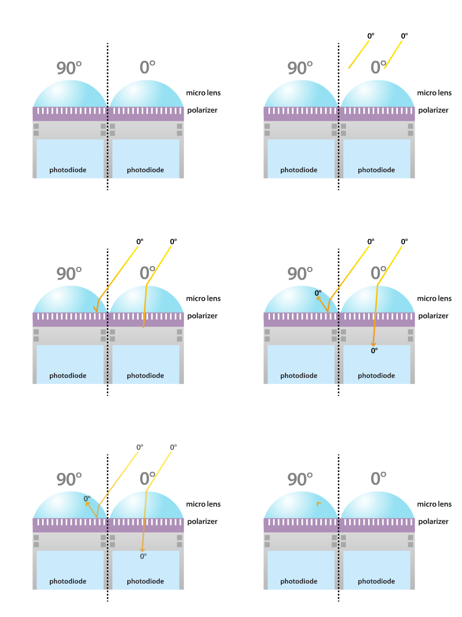
There’s rare case as the below image. In this case, a small part of light ray are refracted into the nearby camera. Personally, i haven’t meet this problem yet, but a problem is a problem so i list it here.
polarization sensor
In 2018, Sony introduce the first ever polarization sensor IMX250MZR source. This is the first polarization sensor in the vision industry. So from now on, we’ll have another choice to work with polarization imaging.
IMX250MZR sensor has the following structure :
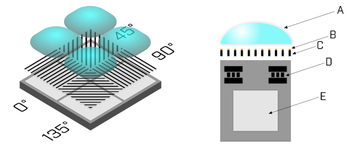
Each pixel has its own polarization filter. These filters are oriented at 0 °, 45 °, 90 °, 135 ° and are arranged to repeat the 2-pixel block. The polarization filter (C) for each pixel is coated with an antireflective layer (B) and placed between the microlens (A) and the photosensitive photodiode (E).
Comparing with polarization lense, polarization sensor could completely remove noise.
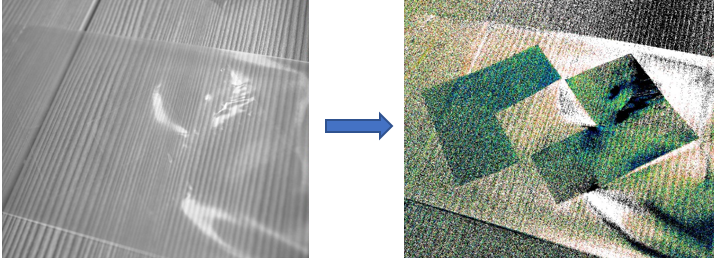
These below picture are capture by using IMX250MZR sensor. Personally, it’s quite impressive result source.


Conclusion
- Polarizating imaging is still a new type of sensor. More time is needed until this sensor is mature enough. But it’s a new cool sensor for computer vision engineer.
Reference
- introduction-to-polarization/
- polarization application
- quora
- sony-polarization sensor
- phan cuc la gi
- lucid vision : explained-sony-polarized-sensor
- Going-Polarized-Presentation
- use case cua polaration imaging
- 08_Stage1_1430_LUCID
- Lucid vision lab white paper
- sony polarization sensor
- Study of birefringence alterations during optical clearing of biological tissues
Leave a comment